English

Understanding OUF-W Converter Types
The OUF-W Series offers various converter models tailored to diverse industrial needs:
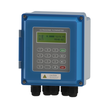
1. OUF-W 2000B (Wall Mount):
o Features: IP65 enclosure, 2×20 LCD display, 16-key interface.
o Ideal For: Control panels, pump stations, and HVAC systems.
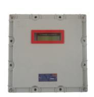
2. OUF-W 2000SW/SD (Explosion-Proof):
o Features: Explosion-proof design and 316L stainless steel housing.
o Ideal For: Oil refineries, chemical plants, and hazardous zones.
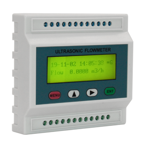
3. OUF-W 2000F (DIN Rail Module):
o Features: Compact design (75mm width), RS485/4-20mA outputs.
o Ideal For: Integration into PLC cabinets or space-constrained environments.
Step-by-Step Installation Guide
1. Wall-Mount Installation (OUF-W 2000B)
• Tools Needed: Drill, Φ6 expansion bolts, level.
• Steps:
1. Mark mounting holes using the converter’s backplate as a template.
2. Drill holes (depth: 50mm) and insert expansion bolts.
3. Secure the converter, ensuring it remains level to avoid display misalignment.
4. For DIN rail mounting, attach rail clamps (included) to the converter’s slots.
Pro Tip:
Leave 100mm clearance around the converter for ventilation and cable management.
2. Explosion-Proof Installation (OUF-W 2000SW/SD)
• Safety Protocols:
o De-energize the area before installation (NFPA 70 compliance).
o Use Φ8 stainless steel bolts to secure the housing to concrete walls.
• Sealing:
o Apply silicone gel to cable glands and junction box seams.
o Torque bolts to 15 Nm for IP66 water resistance.
3. DIN Rail Mounting (OUF-W 2000F)
• Steps:
1. Snap the converter onto a standard 35mm DIN rail.
2. Secure the bottom latch to prevent vibration-induced dislodging.
3. Group signal cables separately from power lines to minimize EMI.
Wiring Diagrams & Best Practices
Key Terminals (OUF-W 2000B Example):
|
Terminal |
Function |
Wire Color |
|
24V+/- |
DC Power Input (8–36V) |
Red/Black |
|
UP+/UP- |
Upstream Transducer |
Red/Black |
|
DN+/DN- |
Downstream Transducer |
Blue/White |
|
RS485+/- |
MODBUS Communication |
Green/Yellow |
|
AO+/AO- |
4-20mA Analog Output |
Brown/Gray |
Wiring Tips:
• Use shielded twisted-pair cables for transducers (max length: 200m).
• Ground the shield at the converter’s GND terminal (resistance <1Ω).
• Separate AC power lines by 30cm from signal cables to reduce noise.
Temperature Sensor Wiring (PT100)
• Connect PT100 probes (T1/T2) to terminals 51-56 for heat measurement.
• For 3-wire PT100s: Match red (excitation), white (signal), and blue (ground) wires.
Common Mistake:
Reversing UP/DN transducer cables causes negative flow readings. Verify labels (UP = red, DN = blue).
Post-Installation Verification
1. Power-Up Test:
o Check for error codes (Menu M08). “R” indicates normal operation.
2. Signal Validation:
o Navigate to M90: Ensure signal strength >60 and Q value >60.
o Use M91 to confirm transmission time ratio (97–103%).
3. Functional Test:
o Simulate flow (e.g., open a valve) and verify readings on M00 (flow rate) and M05 (heat rate).
Call to Action:
Need help with wiring? Contact Kaifeng Oasis for a free site audit to ensure your installation meets industry standards!
Next in the Series
In Article 4: Selecting Transducers for OUF-W Ultrasonic Flowmeters, we’ll compare clamp-on, insertion, and inline models, with sizing charts and temperature/pressure guidelines.

Please contact us for free quotation by form below. We promise the quickest response within 24 hours: